Adjusting the valve clearances on an KTM LC4 (Duke
DIY instruction on how to set the vlve clearances on an LC4
This is a step by step guide on how to set the valve clearances (tappets) on a LC4 engine, Duke II MY06.
Remove seat,
Remove tank by removing one 13mm nut at back of tank.
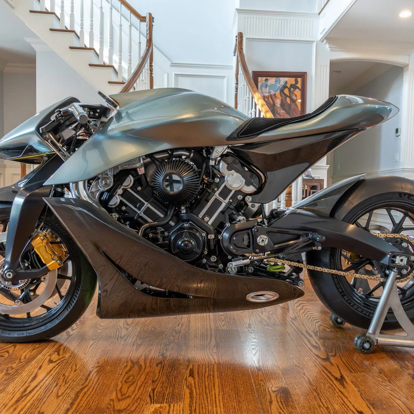
Picture 1

Remove the lower forward 8mm bolt ONLY that holds the radiator side air deflector to the rads, the panel with DUKE written on it. One bolt on each side.
Picture 2

Unplug fuel line from tank making sure it's turned off first, and lift tank at the front first then at the back. Do not remove the side panels fastened to the tank, they lift off with it.
Picture 3

Remove location spigot on left hand side for the fuel tank at the front of the frame, 8mm bolt, and remove completely the breather pipe from exhaust rocker cover to frame, on the left hand side of the engine.
Picture 4

Remove location spigot on right hand side for the fuel tank at the front of the frame, 8mm bolt, and lift decompressor lever at exhaust rocker cover to disengage the nipple on the cable. You may have to turn the engine over with the kick-start slowly to get the valves in a position where the lever will lift easily.
Picture 5

Undo the two 6mm screws which hold the electric fan in place and lift clear, but not remove.
Picture 6

Undo breather pipe from frame to crankcase at frame end upper position only, near the inlet rocker cover.
Picture 7

Remove inlet rocker cover (3 off 8mm bolts) and gasket.
Picture 8

Undo the sparkplug but leave it sat in the head to stop anything falling inside the engine. The washers on the rocker cover bolts are small and could easily fall in.
Remove the exhaust rocker cover, (3 off 8mm bolts) and gasket, and detach it from the decompressor cable.
Use kick-start to get inlet fully open then adjust exhaust valves.
Use kick-start to get exhaust fully open then adjust inlet valves.
You cannot really check them as the rocker adjustment screw has a self aligning swivel pad on the end and it rocks when you try and slide a feeler gauge in position.
Just undo the lock nut (10mm), screw the adjuster screw well out then position the feeler gauge (0.15mm) and screw back until it is just nipped by the adjuster screw.
Tighten the locknut, and repeat for remaining valve.
Make sure the feeler slides out without too much restriction after locking up the adjuster screw.
The screw tends to stay in position when you lock it and often you do not need to hold it still with a screwdriver, which is handy because it is tight for space.
It's a bit fiddly, but with a cranked feeler gauge it's possible.
Just use a single feeler gauge removed from the bunch.
This isn't my picture, but it shows the swivel pad quite well, but the feeler gauge is difficult to see.
These are the exhaust valves.
Picture 9

Same valves viewed from the opposite side.
Picture 10

In the immortal words of any Haynes manual, re-assembly is simply a reverse of the above procedure, but degrease the gaskets and both mating faces of the cover and the head with brake cleaner or similar before re-fitting to stop them leaking.
Cheers
MTR
Sponsored By

Britain's No.1 Specialist Tools and Machinery Superstores
When it comes to buying tools and machinery, you need to know you're buying from specialists who know what they're talking about.
Machine Mart eat, sleep and breathe tools and machinery, and are constantly updating their range to give you the very best choice and value for money - all backed by expert advice from their friendly and knowledgeable staff. With superstores nationwide, a dedicated mail order department and a 24 hour website offering quality branded items at fiercely competitive prices, they should be your first choice for quality tools and equipment.